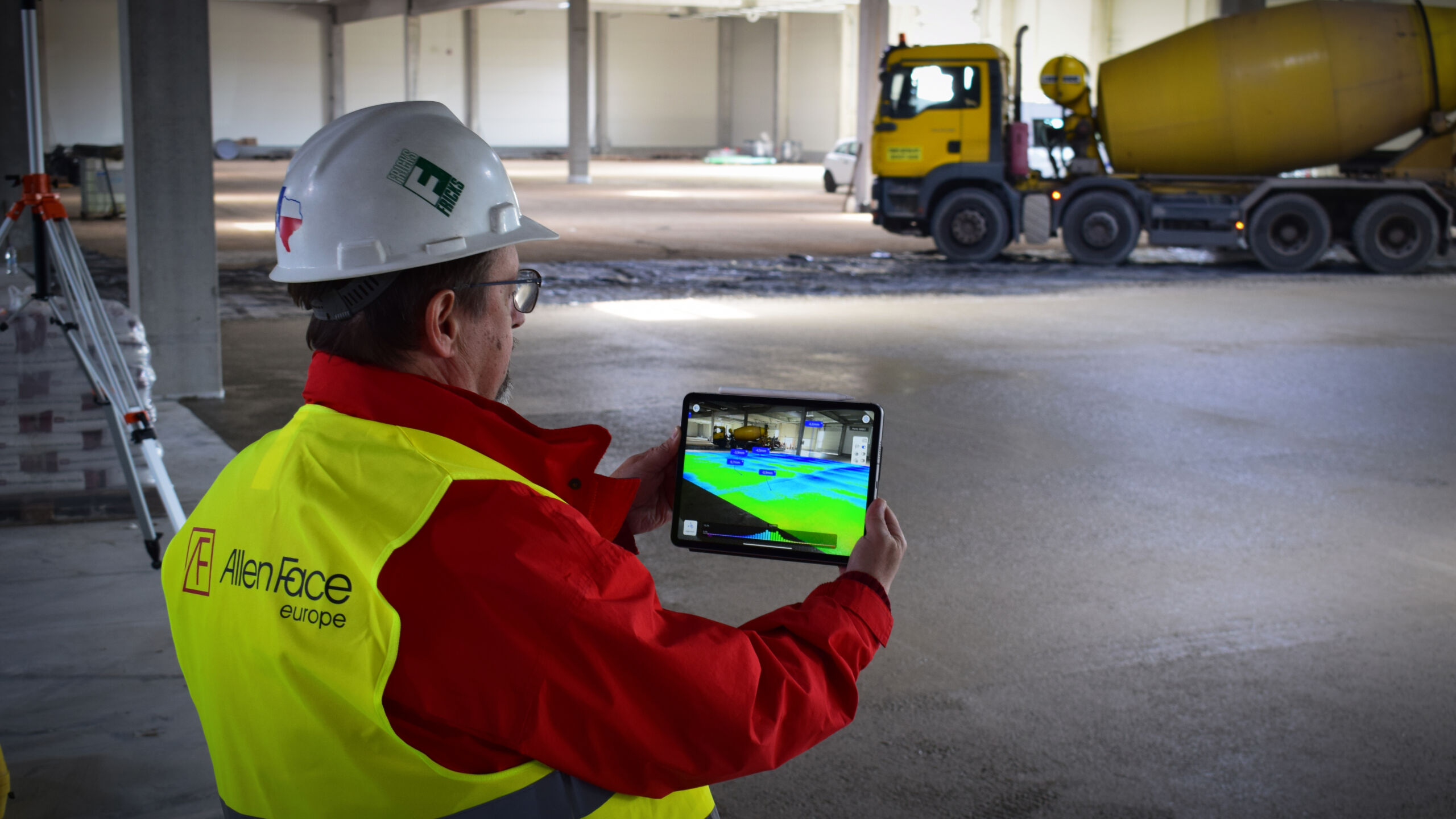
Project management purposes of Random Traffic floors, certifications.

The flatness and levelness of the formed floor surface are directly related to the associated costs(storage efficiency, rotation speed, forklift operating expenses.)and processes that can be implemented in the warehouse/manufacturing part.

The more flat the surface of an industrial floor, the more widely it is used at a lower cost.

All straightedge type floor specifications (like DIN 18 202) are based upon an obvious mathematical impossibility: the false notion that a two-dimensional object(like the floor’s profile) can be discriminated by a single parameter(“gap under the straightedge”). (is very difficult to carry out in terms of measurement technology and does not provide usable information on floor flatness)

It is a proven fact that impossible to control any floor’s shape profile with a single measured parameter of “gap under the straightedge.”

The FF / FL system controls the waves on the floor. FF (Flatness) numbers control the floor’s local bumpiness. FL (Levelness) numbers control the floor’s local inclination relative to horizontal. The higher the floor’s FF and FL numbers, the better its flatness and levelness. It offers an easy- to-follow and precise procedure for determining the actual floor profile for contractors and investors, preventing future disputes.

Essential features of FF / FL system:

  • its statistical method of measurement according to clear rules gives an authentic, always verifiable result from the surface
  • makes the measured surfaces comparable
  • simple measurement, easy to apply
  • it also provides control over the floor construction process
  • provides design professionals and engineers with reliable data on the planned function of the floor
  • with a reasonable solution, it provides reliable data on the flatness of the floor at a competitive price

Tools of FF/FL measurements:

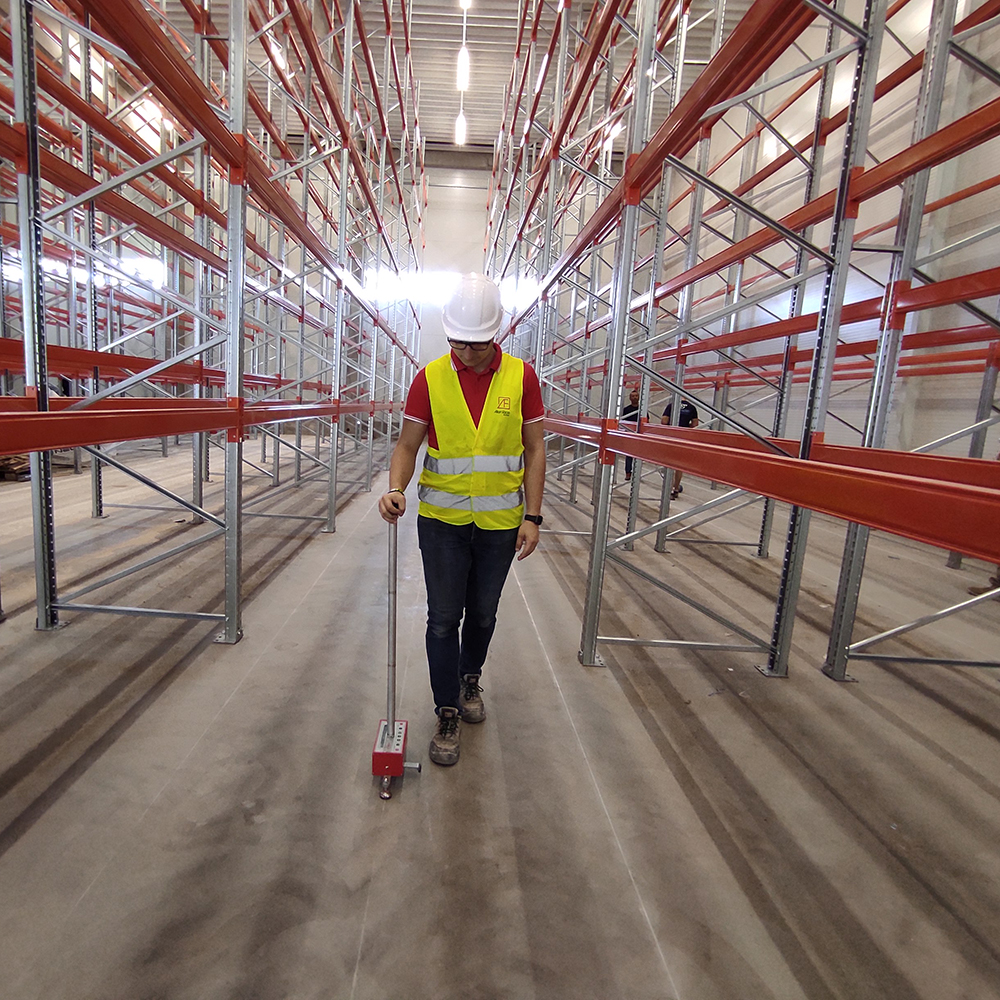
The measuring devices are the D-meter and the F-meter profiling measuring instruments.

With their help, anyone can easily measure the floor surface and get information on floor flatness.

You can find more information about the system and its applicability under the downloads tabs.

Getting info about corrective grinding technology, click here.

Determination of the surface regularity of Defined Traffic floors using the Fmin system

Man operating forklift in a very narrow aisle in a warehouse

Every floor falls into one of two use categories for controlling profile quality: defined traffic or random traffic.

All floors supporting the operation of any fixed-path vehicle system (e.g., a wire or rail-guided narrow aisle lift truck) are deemed Defined Traffic floors. All floors that are not categorized as Defined Traffic are automatically deemed Random Traffic floors.

VNA (very narrow aisle) warehouses

In Defined Traffic systems, lift-truck traffic occurs in narrow aisles along a defined route. The service capacity of such warehouses (measured by pallets per truck per hour) depends to a large extent on the values ​​of shortwave (FF = flatness) and horizontal (FL = levelness) in the truck’s wheel track.

Understandably, manufacturers are pushing for forklifts to increase warehouse utilization, so producing forklifts

for higher speed operation

increase their stability

to serve ever-increasing racks heights to increase efficiency as well

Meeting these conditions written above can only be achieved by moving on much flatter and more level floors as usual.
If the track (the part of the industrial floor on which the truck is moving) is wavy, the truck will be shaking, and the truck operator will reduce speed to allow the lift truck to drive safely. Thus, the same amount of pallets can only be moved with enlarged trucks at a reduced speed rate (this means a significant increase in warehouse operating costs).

  • Effect of the superflat industrial floor on the forklifts
  • Effect of the superflat industrial floor on the forklifts 3
Animation of how the D-meter works

D-Meter employs a sophisticated 3_D analysis program to compute the minimum amount of grinding required to bring the wheel tracks into full,6-dimensional, simultaneous compliance with the specified Fmin number.

The proprietary Fmin system ( developed by Mr. Allen Face in 1979) limits the allowable transverse and longitudinal tilt, angular rotations, and angular accelerations (6 variables in total) that occur when moving on an existing fixed track a particular lift truck. For this reason, the permissible values ​​of the variables responsible for the transverse and longitudinal movements and the truck’s dynamic and static effects must be specified and limited.

The allowable values ​​of these variables are “compressed” into a single dimensionless parameter-the Fmin number-wich sets the largest cross aisle(transverse) and down- aisle(longitudinal) ride roughness and mast tilt values to be tolerated. The higher the Fmin number, the higher the accuracy, the lower the tolerance thresholds for shortwave and horizontality.

The required Fmin number for a particular truck geometry(known wheel configuration) in a given aisle to ensure optimum truck speed is determined from the truck geometry, the aisle length, and the maximum lift height: details contain the Fmin specification.

Fmin is thus a full-fledged Vehicle Simulation System that controls the the truck’s statics and dynamics at all locations within the aisle (side-to-side and front-to back tilt, angular velocity, and angular acceleration).

Thus, the Fmin system is the only system that can control the the truck’s static and dynamic motion conditions in wheel tracks with the correct flatness of the floor surface at the lowest cost.

Measuring floor flatness and accuracy with D-meter in a hall

Fmin measuring

Showcasing how the D-meter walking profiler works

Defined – easy-to-learn – D-meter measuring method drives in wheel tracks in narrow aisles using a fixed pattern to create a complete set of vertically correlated wheel track profiles. It collects data in 30 cm increments in each track. From the data recorded by the device, Fmin Analysis Software generates reports that detail the aisle’s condition. We can get vis-a-vis all the six Fmin tolerances along the aisles’ entire length and the depth of grinding required at each spot to bring the wheel tracks into full compliance with the specified Fmin. The Grinding Optimization Program(GrOpt) gives the amount of grinding needed for a given location along the wheel tracks.

After measuring and evaluating the total length of the aisle at which point and how much grinding is required, can create the aisle surface for optimal truck movement with corrective grinding.

Corrective grindings in the VNA system

If you launch a project and have questions about the cost estimation, contact us!